DHT11
简介
DHT11 是一个比较常见的温湿度传感器,只使用了一个 DATA 接口实现了单总线与主机的通信,一次传送40位数据, 高位先出。
DHT11 说明书
数据定义
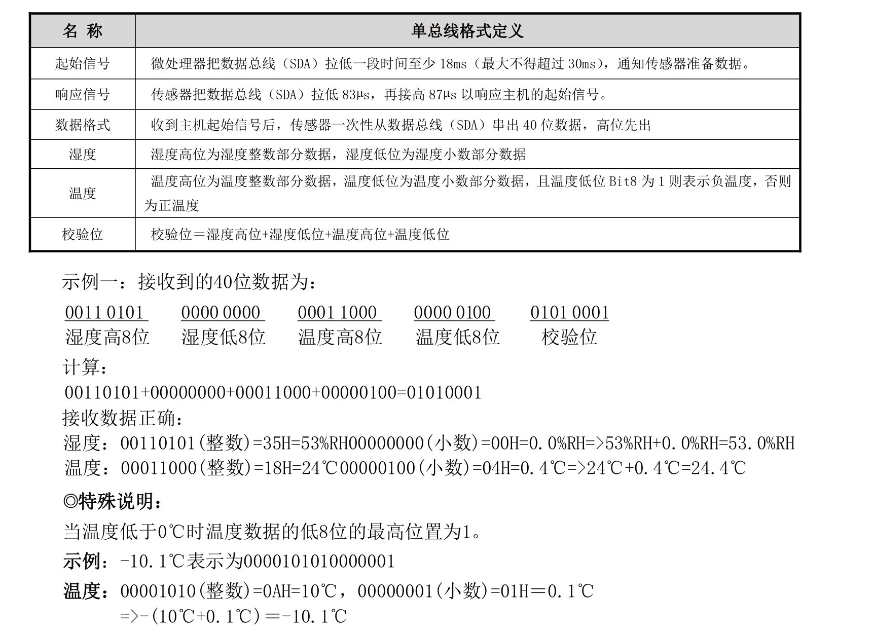
数据格式: 8bit湿度整数数据+8bit湿度小数数据+8bit温度整数数据+8bit温度小数数据+8bit校验位。
注:其中湿度小数部分为0。
校验位数据定义为 “8bit湿度整数数据+8bit湿度小数数据+8bit温度整数数据+8bit温度小数数据”。8bit校验位等于所得结果的末8位。
由此,我们可以对数据进行以下定义:
1
2
3
4
5
6
7
8
9
| // DHT11数据结构
typedef struct {
uint8_t humity; // 湿度整数部分
uint8_t temp; // 温度整数部分
uint8_t humity_dec; // 湿度小数部分 (DHT11固定为0)
uint8_t temp_dec; // 温度小数部分
uint8_t check; // 校验和
_Bool negative; // 是否为负数
} dht11_dt;
|
通信
初始化
DHT11上电后(DHT11上电后要等待 1S 以越过不稳定状态在此期间不能发送任何指令),测试环境 温湿度数据,并记录数据,同时 DHT11的DATA数据线由上拉电阻拉高一直保持高电平;此时 DHT11的 DATA 引脚处于输入状态,时刻检测外部信号。
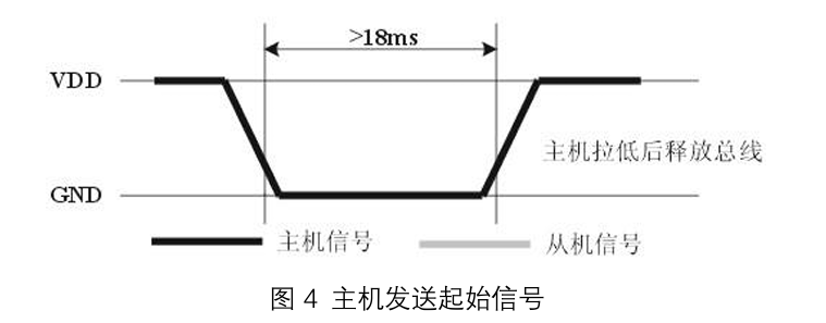
微处理器的I/O设置为输出同时输出低电平,且低电平保持时间不能小于18ms(最大不得超过30ms), 然后微处理器的I/O设置为输入状态,由于上拉电阻,微处理器的I/O即DHT11的DATA数据线也随之变高,等待DHT11作出回答信号,发送信号如图所示:
由此,我们便可以设计初始化代码,但是在此之前,我们需要先来看一下对于其数据端口操作的定义:
 1
 2
 3
 4
 5
 6
 7
 8
 9
10
11
12
13
14
15
16
17
18
19
20
21
22
23
24
25
26
27
28
29
30
31
32
33
34
35
36
| // DHT11 GPIO
#define DHT11_GPIO_PORT GPIOC
#define DHT11_PIN_NUM 4
#define DHT11_GPIO_PIN (1 << DHT11_PIN_NUM)
#define DHT11_GPIO_CLK RCC_APB2ENR_IOPCEN
// Set the PIN to Input with pull-up / pull-down Mode ( 0x8 -> 0b1000 )
#define DHT11_IO_IN() do { \
if(DHT11_PIN_NUM < 8) { \
DHT11_GPIO_PORT->CRL &= ~(0xF << (DHT11_PIN_NUM * 4)); \
DHT11_GPIO_PORT->CRL |= (0x8 << (DHT11_PIN_NUM * 4)); \
} else { \
DHT11_GPIO_PORT->CRH &= ~(0xF << ((DHT11_PIN_NUM - 8) * 4)); \
DHT11_GPIO_PORT->CRH |= (0x8 << ((DHT11_PIN_NUM - 8) * 4)); \
} \
} while(0)
// Set the PIN to Push-pull Output Mode ( 0x3 -> 0b0011 )
#define DHT11_IO_OUT() do { \
if(DHT11_PIN_NUM < 8) { \
DHT11_GPIO_PORT->CRL &= ~(0xF << (DHT11_PIN_NUM * 4)); \
DHT11_GPIO_PORT->CRL |= (0x3 << (DHT11_PIN_NUM * 4)); \
} else { \
DHT11_GPIO_PORT->CRH &= ~(0xF << ((DHT11_PIN_NUM - 8) * 4)); \
DHT11_GPIO_PORT->CRH |= (0x3 << ((DHT11_PIN_NUM - 8) * 4)); \
} \
} while(0)
// Set the output of the DHT11 PIN
#define DHT11_DQ_OUT(x) do { \
if(x) DHT11_GPIO_PORT->BSRR = DHT11_GPIO_PIN; \
else DHT11_GPIO_PORT->BRR = DHT11_GPIO_PIN; \
} while(0)
// Read the input of the DHT11 PIN
#define DHT11_DQ_IN (DHT11_GPIO_PORT->IDR & DHT11_GPIO_PIN)
|
然后,就可以实现:
 1
 2
 3
 4
 5
 6
 7
 8
 9
10
11
12
13
14
15
16
17
18
19
20
21
22
23
24
25
26
| // Reset DHT11. (其实就是向DHT11发送起始信号)
void dht11_rst(void)
{
DHT11_IO_OUT(); // SET OUTPUT
DHT11_DQ_OUT(0); // 拉低 DQ
delay_ms(20); // 拉低至少18ms
DHT11_DQ_OUT(1); // 拉高 DQ
delay_us(20); // 主机拉高20~40us
}
// Init DHT11
uint8_t dht11_init(void)
{
// 使能 DHT11 所在 Pin 的时钟
RCC->APB2ENR |= DHT11_GPIO_CLK;
// 配置GPIO为推挽输出
DHT11_IO_OUT();
DHT11_DQ_OUT(1);
// DHT11需要上电后至少1秒才能稳定
delay_ms(1500); // 等待1.5秒确保稳定
dht11_rst();
return dht11_check();
}
|
其中,delay_ms 是通过 SysTick 实现的毫秒延迟函数,实现方案可以看看
检查连接状态
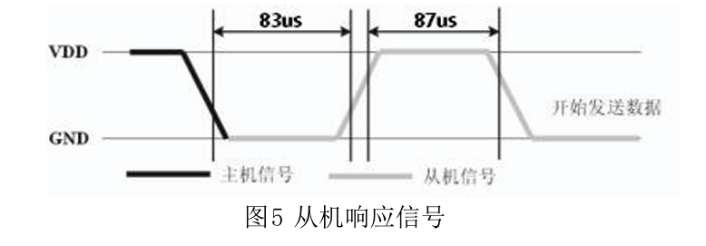
DHT11的DATA引脚检测到外部信号有低电平时,等待外部信号低电平结束,延迟后DHT11的 DATA引脚处于输出状态,输出83微秒的低电平作为应答信号,紧接着输出87微秒的高电平通知外设准备接收数据,微处理器的I/O此时处于输入状态,检测到I/O有低电平(DHT11回应信号) 后,等待87微秒的高电平后的数据接收,发送信号如图5所示
 1
 2
 3
 4
 5
 6
 7
 8
 9
10
11
12
13
14
15
16
17
18
19
20
21
22
23
24
25
26
27
28
29
30
| /**
* @brief Check the connectivity between DHT11 and MCU.
* @return status code
* - 0 Success.
* - 1 Timed out.
*/
uint8_t dht11_check(void)
{
uint16_t retry = 0;
DHT11_IO_IN(); // SET INPUT
// 等待DHT11拉低(响应信号开始)
while (DHT11_DQ_IN && retry < 1000)
{
retry++;
delay_us(1);
}
if(retry >= 1000) return 1; // 超时,DHT11没有响应
retry = 0;
// 等待DHT11拉高(响应信号结束)
while (!DHT11_DQ_IN && retry < 1000)
{
retry++;
delay_us(1);
}
if(retry >= 1000) return 1; // 超时
return 0;
}
|
delay_us 是使用 TIM 基本计时器实现的微秒级延迟函数,下面会介绍到。
读取数据
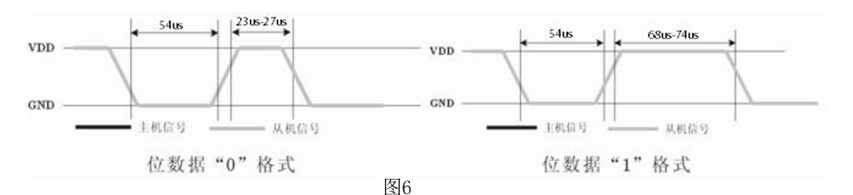
由DHT11的DATA引脚输出40位数据,微处理器根据I/O电平的变化接收40位数据,位数据 “0”的格式为:54微秒的低电平和23-27微秒的高电平,位数据“1”的格式为:54微秒的低 电平加68-74微秒的高电平。位数据“0”、“1”格式信号如图6所示:
根据上面数据定义,我们需要一位一位的读取,并把内容放在5个 uint8_t 的数据中,所以我们可以这样写:
 1
 2
 3
 4
 5
 6
 7
 8
 9
10
11
12
13
14
15
16
17
18
19
20
21
22
23
24
25
26
27
28
29
30
31
32
33
34
35
36
37
38
39
40
41
42
43
44
45
46
47
48
49
50
51
52
53
54
55
56
57
58
59
60
61
62
63
64
65
66
67
68
69
70
71
72
73
74
75
76
77
78
79
80
81
82
83
84
85
86
87
88
89
90
91
92
93
94
95
96
97
| // 通过缓冲区内的数据保存好内容数据
static uint8_t save_data_from_buf( uint8_t *buf, dht11_dt *dest ) {
// 零下的温度在缓冲区内最高位为 1
dest->negative = ((1<<7) & buf[3]) ? 1 : 0;
dest->temp = buf[2];
// 把零下温度最高位的1排除掉
dest->temp_dec = ~(1<<7) & buf[3];
dest->humity = buf[0];
dest->humity_dec = buf[1];
dest->check = buf[4];
return 0;
}
static uint8_t dht11_read_bit(void)
{
uint16_t retry = 0;
// 等待变为低电平(每个位开始)
while(DHT11_DQ_IN && retry < 100)
{
retry++;
delay_us(1);
}
if(retry >= 100) return 0; // 超时,返回0
retry = 0;
// 等待变高电平(数据位)
while(!DHT11_DQ_IN && retry < 100)
{
retry++;
delay_us(1);
}
if(retry >= 100) return 0; // 超时,返回0
// Bit 0 -> 23-27us 高电平
// Bit 1 -> 68-74us 高电平
// 如果高电平持续时间较长,则为'1',否则为'0'
// 延时50ms后检测当前为高电平还是低电平
// 不能使用 delay_us(1) 来计算持续了多少微秒
// 因为在 1us 时间内 delay_us 调用的时间就已经远大于 1us
delay_us(50);
if(DHT11_DQ_IN) return 1;
else return 0;
}
static uint8_t dht11_read_byte(void)
{
uint8_t i, dat;
dat = 0;
// 1 byte <- 8 bit
for (i = 0; i < 8; i++)
{
dat <<= 1;
dat |= dht11_read_bit();
}
return dat;
}
/**
* @brief Read data from DHT11
* @param datavalue A pointer to the dest where receives the data.
* @return status code
* - 0 Success.
* - 1 Failed to connect with DHT11.
* - 2 Checksum failed.
*/
uint8_t dht11_read(dht11_dt *datavalue)
{
uint8_t buf[5];
uint8_t i;
dht11_rst();
uint8_t check_result = dht11_check();
if(check_result == 0)
{
for(i = 0; i < 5; i++)
{
buf[i] = dht11_read_byte();
}
uint8_t checksum = buf[0] + buf[1] + buf[2] + buf[3];
if ( checksum == buf[4] ) {
save_data_from_buf(buf, datavalue);
}
// 0 -> Success, 2-> Checksum falied.
return ( checksum == buf[4] ) ? 0 : 2;
}
else
{
return 1; // Failed to communicate with DHT11.
}
}
|
这里最有坑的地方就是检测一个 bit 内后面高电平的部分,我一开始的写法是使用 delay_us(1) 来每过1us统计高电平持续了多久,但是这样写就会出现严重问题:函数调用本身,以及进行读取操作,都是会占用时间的,造成了对于延迟 1us 来说,其函数调用以及内部实现的开销就已经达到了约 1.5us 左右,造成计时严重问题。所以在实际开发中,要避免使用 delay_us(1) 这样的极短时间作为计数,因为对于极短的时间来说损耗是极大的。
TIM 基本计时器
STM32F103 集成了多个 TIM,可以实现很多功能。其中,TIM 6 和 7 是基本计时器 (Basic Timers)。
我们接下来实现一个最基本的微秒计时功能。TIM的基本知识可以看看这个:https://www.bilibili.com/video/BV11u4y1A7gS
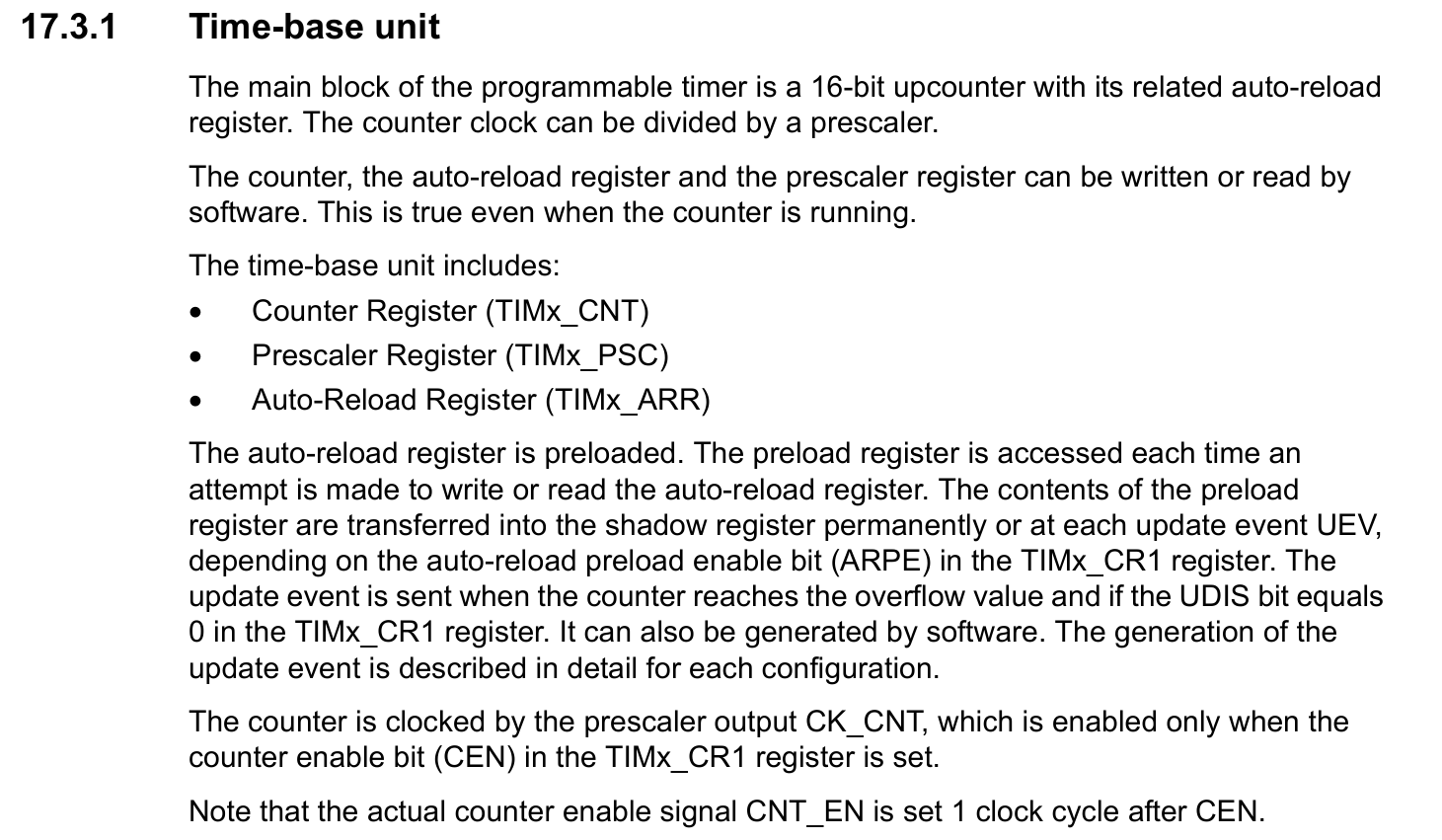
我们实现的微秒计时器没有用到中断以及任何高级功能,所以只需要设置基本的 Time-base unit:
 1
 2
 3
 4
 5
 6
 7
 8
 9
10
11
12
13
14
15
16
17
18
19
20
21
22
23
24
25
26
27
28
29
30
31
32
33
34
35
36
37
38
39
40
41
42
43
44
45
46
47
48
49
50
51
52
53
54
55
56
57
58
59
60
61
62
63
64
65
66
67
68
69
70
71
72
73
74
75
76
77
78
79
80
81
| #include "delay.h"
#include "stm32f10x.h"
#include <stdbool.h>
#include <stdint.h>
/* SysTick */
volatile uint32_t systick_counter = 0;
volatile bool is_delay_inited = false;
void delay_init() {
if ( is_delay_inited ) return;
/* SysTick Init */
SysTick->CTRL |= SysTick_CTRL_ENABLE |
SysTick_CTRL_TICKINT |
SysTick_CTRL_CLKSOURCE;
/* Our MCU is at 72MHz, so set load to this for 1ms timer */
SysTick->LOAD = 72000 - 1;
SysTick->VAL = 0;
/* TIM6 Init */
// 使能TIM6时钟
RCC->APB1ENR |= RCC_APB1ENR_TIM6EN;
// 重置TIM6并清除重置位
RCC->APB1RSTR |= RCC_APB1RSTR_TIM6RST;
RCC->APB1RSTR &= ~RCC_APB1RSTR_TIM6RST;
// 配置TIM6
TIM6->PSC = 72 - 1; // 预分频 72,即相当于 1us timer
TIM6->ARR = 0xFFFF;
TIM6->CNT = 0;
// 启动定时器
TIM6->CR1 |= TIM_CR1_CEN;
is_delay_inited = true;
}
void SysTick_Handler() {
++systick_counter;
}
uint32_t delay_get_tick() {
if ( !is_delay_inited ) delay_init();
return systick_counter;
}
void delay_ms(uint32_t ms) {
if ( !is_delay_inited ) delay_init();
uint32_t start = systick_counter;
while (systick_counter - start < ms);
return;
}
// t: expiration time, prd: period, now: current time. Return true if expired
bool timer_expired(uint32_t *t, uint32_t prd, uint32_t now) {
if ( !is_delay_inited ) delay_init();
if (now + prd < *t) *t = 0; // Time wrapped? Reset timer
if (*t == 0) *t = now + prd; // First poll? Set expiration
if (*t > now) return false; // Not expired yet, return
*t = (now - *t) > prd ? now + prd : *t + prd; // Next expiration time
return true; // Expired, return true
}
void delay_us(uint16_t us) {
if ( !is_delay_inited ) delay_init();
if (us == 0) return;
uint16_t start = TIM6->CNT;
uint16_t target = start + us;
// 检查是否会发生溢出
if (target > start) {
// 无溢出情况:直接等待
while (TIM6->CNT < target && TIM6->CNT >= start);
} else {
// 会发生溢出:先等到溢出,再等到目标值
while (TIM6->CNT >= start); // 等待溢出
while (TIM6->CNT < target); // 等待到目标值
}
}
|
这里使用了循环检测 TIM6->CNT,而不是使用中断,是因为对于特别低的时间来说,使用中断是不合适的。
总结
一定要注意 delay_us 函数调用本身也是有开销的,对于 ms 的时间来说影响比较小,但是对于 us 来说这是不可忽视的,所以一定要谨慎使用。